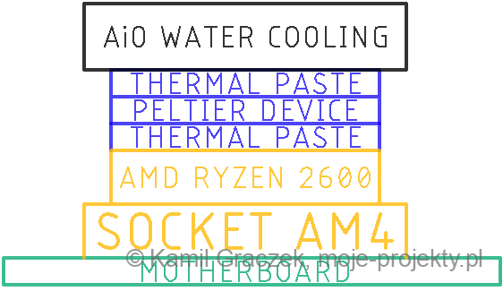
AMD RYZEN 5 2600 cooler with Peltier module
Introduction
A manufacturer of computer parts presented in 2020 AiO with a Peltier module built into the water block. The price of this set was very high, but the idea seemed to be quite good.
Below I present a report on the modernization of my AiO set consisting in adding a Peltier device to the cooling system
PC technical parameters
Motherboard
Processor
Model: AMD Ryzen 5 2600 3,4GHZ 16 MB
Graphics card
Model: ASUS Radeon RX 580 Dual OC 8GB GDDR5
RAM memory
Hard drives
Model: XPG GAMMIX S5 238.5 GB NVMe
Power Supply
Computer case
Other
Corsair H100i Pro – zestaw AIO 2x120mm
Proposed cooling solution
The test uses an AMD processor dedicated to work with the AM4 socket, a 136W thermocouple and an AiO cooling set. I started the assembly of the Peltier module from its thorough cleaning of the remnants of silicone sealant. Any unevenness on the surface adjacent to the processor significantly increases the thermal resistance of the connection, and thus increases the temperature of the cooled element.
I moved the factory cooling mount away from the motherboard using plastic sleeves. The sleeves should have an inner diameter of approximately 4mm and an outer diameter of 10-15mm. Length depends on the thickness of the thermoelectric cooler.
The thermally conductive paste was placed between the processor and the cold side of the cell and between the warm side and the AiO pump.
I connected the wires powering the thermocouple to a semiconductor relay (SSR, K1 in the diagram), and the relay to the converter increasing the voltage from 12 to 14V (V1 in the diagram). The relay control signal comes from the 4 pin fan socket. To be able to use the fan connector, you must first set the operating parameters in the BIOS (UEFI).
Thermoelectric Cooler (TEC)
Maximum working temperature 200 * C
Base plate material: Al2O3 (19-30 W / m * K)
Maximum cooling heat output 136 W
The highest input voltage 15.4 V
Maximum current 15A
Resistance 0.88R at 50 * C
3.3mm thick (you need to move the factory processor mount away from the motherboard by the thickness of the cooling module)
Assuming data for calculations:
TCPU = 30 * C
TAiO = 40 * C
DT = 10 * C
QCPU = 65W
According to the graph Qc = f (DT), we need to supply about 6 amps to the module, which is consistent with the values obtained in real tests.
Such values of currents are possible to obtain with a voltage on the cell of about 14 V. In the diagram of the cell efficiency COP = f (V), the value of 14 V corresponds to the COP coefficient (Coefficient Of Performance is the ratio between the thermal power of the cell and the electrical power supplied to its power supply). ) equal to 0.7.
Power delivered to the module: 14V * 6A = 84W
Power dissipated from the cold side: 84W * 0.7 (COP) = 58.8W
Power to be dissipated by cooling on the hot side: 84W + 58.8W = 142.8W
Pre-modification tests
The CPU temperature when loaded with the synthetic OCCT test was 39 ° C after 3 minutes of testing.
The processor and the rest of the PC components worked stably, and the cooling coped well with heat dissipation. The temperature of the CPU without load fluctuated in the range of 30-34 * C depending on the ambient temperature.
Post-upgrade tests
Using a 136-watt Peltier module, the processor temperature increased compared to the chip without additional components between the processor’s IHS and the cooling.
The comfort of using the computer has decreased, because the fans in the AiO set work with noticeably higher speed, and in return we get higher processor temperatures 🙂
Current consumption by the Peltier module
Below is the waveform of the voltage and current flowing through the Peltier module. The power delivered to the module was approximately 90 W.
The Seebeck effect is visible in the current diagram. At the moment of switching off the SSR, the current flows in the opposite direction (the i marker [A] is 0 V). This is due to the formation of an electromotive force when the cold side of the thermocouple was colder than the hot side. The current flow was possible due to the presence of a surge suppression diode in the SSR.
The reasons for the failure of this cooling method
The processor that was tested had a TDP of 65 W, which was the value that water cooling could handle without any problems. However, when the current flowed through the Peltier cell, an additional 90 W had to be discharged from the hot side of the module. The AiO set that I have was badly able to dissipate over 150 W in the form of heat. In addition, the disadvantage of this system is the fact that there are several additional thermal resistances due to the imperfections of the Peltier module and an additional layer of thermal paste.
Starting the computer without the attached Peltier module causes a rapid increase in the temperature of the processor.
Summary
Below is a brief summary of the advantages and disadvantages of CPU cooling using a Peltier module.
ADVANTAGES
- Lower temperatures without load
DISADVANTAGES
- Additional energy losses necessary to power the module
- Higher temperatures under load
- The fans run at higher speed
- TEC Requires appropriate control
In my opinion, using Peltier modules in a PC is ineffective. It requires a large amount of heat to be dissipated with measurable benefits.
By using a different model of a cell with better efficiency and lower thermal resistance, it would be possible to obtain better results. Changing the control method to PWM control depending on the CPU temperature would also increase the efficiency of the system. The use of more efficient cooling of the warm side of the cell would significantly reduce the temperature of the processor.