
Isolation transformer in an electronics workshop
What are the applications of the isolation transformer?
The isolation transformer is used to isolate the load from the power source. The separation causes that the receiver is galvanically isolated from the supply system. The value of the first short-circuit current depends on several factors:
– installation status;
– installation lengths;
– system voltage.
For example:
With a voltage of 230V, an 800VA isolation transformer and an installation length of about 5m, the short-circuit current is less than 0.5 mA. However, in the case of extensive installations or when the transformer or installation is in bad condition, the current can be much higher. The separation transformer works in the same way as a normal transformer.
The differences in construction usually consist in separating the winding and the primary winding in such a way that damage to the insulation of the winding wires, e.g. due to overheating of the transformer, does not cause a short-circuit between the primary and secondary sides. Between the primary and secondary windings there may be a grounded shielding, which in the above situation causes the protection to trip. This shielding reduces the inter-winding capacitance.

The inside of my isolation transformer.
On the left side you can see an overcurrent circuit breaker – a factory-fitted fuse, as on the right side.
Short-circuit current limitation
Short-circuit for a transformer is an operating condition associated with the “short-circuit voltage” parameter.
By definition, the short-circuit voltage is the voltage applied to the primary terminals of the transformer, with the secondary terminals shorted at the same time, causing the flow of the rated current.
Depending on the design of the transformer, this value ranges from a few to several dozen percent.
The greater the power of the transformer, the greater the short-circuit current at the same short-circuit voltage.
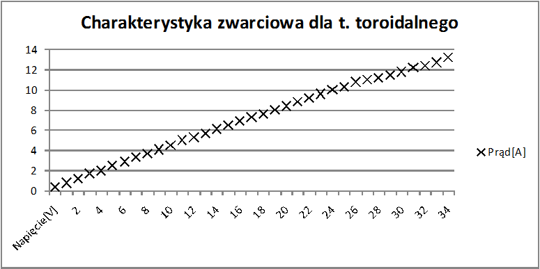
For example, determining the short-circuit voltage of an 800VA transformer:
With the power off, the secondary terminals were shorted with an ammeter. The voltage was slowly increased with an autotransformer at the primary terminals of the tested transformer. The primary voltage was measured with a voltmeter. At the rated current, the voltage was read: 39.2V / 3.5A.
If someone doesn’t have an autotransformer, a step-down transformer will suffice. The dependence of the short-circuit voltage is linear, therefore this parameter can be determined for a value lower than the rated value (it also does not matter whether it is forced from the primary side and shorted from the secondary side or vice versa).
An exemplary sep. transformer 800VA has short-circuit voltage:
\(u_{z%}=\frac{U_1}{U_n}*100% = \frac{39.2}{230}*100%=17%\)Uz% – voltage percentage short-circuit [-]
U1 – measured short-circuit voltage [V]
Un – transformer rated voltage [V]
By greatly simplifying the calculations, the current limitation by such a transformer will be:
\(I_z=Un\div \frac{U_1}{I_2}=230V\div\frac{39.2V}{3.5A}=20.54A\)Iz – estimated short-circuit current [A]
I2 – test short-circuit current [A]
In TN receiving networks, the short-circuit current usually reaches values of the order of 200-500A. The current causing rapid tripping of the overcurrent circuit breaker starts from 30A (for B10 circuit breaker). During a metallic fault without an isolation transformer, a current of 200A will trigger protection B10.
The same short-circuit, but with an isolation transformer which constitutes a significant impedance in the circuit, will result in a current flow of less than 20.54 A, which is well below the activation threshold of the fast element of the installation protection.
At this point, I would like to draw attention to the legitimacy of the protection at the transformer input, because with an overload duration of 40 s and a current of 20 A (read from the B10 protection characteristics), the 800 VA transformer would most likely be thermally damaged.
Voltage ratio of the separation transformer
The transformer in the example has a voltage ratio of 220/220 V/V, you can guess that the number of turns in the primary and secondary windings is the same, which is not true.
In order to compensate for voltage drops on the winding impedance during the flow of operating current, the secondary winding has a few more windings. This is easy to detect by examining the voltage ratio “in both directions”.
Does an isolation transformer eliminate the risk of electric shock?
There is a real risk of electric shock in a circuit powered by an isolation transformer. The condition of the insulation of the transformer, network and receiving devices should be monitored, because the deterioration of their insulating properties results in an increase in the short-circuit current.
The worst case is a short circuit of one of the phase conductors to earth. The first fault current resulting from the network impedance is too small to cause the overcurrent protection to trip.
An earth fault, e.g. in the L1 phase of a three-phase transformer, will cause a voltage of 400V on the L2 and L3 phases relative to the earth, and 230V on the neutral conductor (in IT networks, the N conductor is not earthed directly).
Due to the fact that at the terminals of 1-phase isolation transformers. there is a voltage of 230V, and in 3-phase. 400V, touching two live conductors at the same time is dangerous.
What is your experience with isolation transformers?
Share your opinion in the form below 🙂